Say the same sentence into a phone held at your lips and then from across the kitchen. The words are identical. The first sounds close, warm and dry, like a podcast. The second sounds like a kitchen: hard, hollow, a little far away. Nothing about your voice changed. What changed is how much of the sound reaching the microphone came straight from you and how much bounced around the room first.
Every recording engineer lives inside that observation. A mixing desk can shape a sound later, but it cannot put back what the microphone never heard, and it cannot take out a room that was recorded along with the voice. So the craft of recording is a handful of physical choices made with a stand and a cable: what kind of microphone, which way it faces, how far away, how many, and how loud the signal is when it enters the chain.
This piece covers those choices for two readers at once: the sound engineer, who studies it in year 2, and the producer who records their own band in a bedroom. The ideas are the same. The numbers below are computed live, so you can feel each one move.
- Who takes it
- Year 2 of the Sound Engineering major, and year 4 of the Music Production specialization of Music, where it is the recording course. Audio and music-technology degrees such as Surrey's Tonmeister, Berklee's Music Production and Engineering and Miami's Music Engineering Technology all teach microphones early, usually with a lab.
- What it is for
- Capturing a sound source with the right character, the right balance of direct sound and room, and enough signal above the noise.
- Comes after
- Acoustics, Tuning & Timbre (35/68), which explains waves, decibels and overtones.
- Leads to
- Live Sound Reinforcement (36/66), where the same microphones fight feedback on a stage. It sits beside Digital Audio & the DAW (36/62), where the signal lands, and feeds Mixing & Signal Processing (36/63).
- What this piece gives you
- You will not be able to run a session after reading it. You will know why a cardioid boosts bass up close, why two microphones on one drum can cancel each other, and why "just turn the gain up" has a price. Easier first reads: Music Technology & Production (35/73), How Recording Changed Music (Music 10), and Waves and Sound: What Happens When Two Notes Meet (Physics 13).
Transduction: three ways to turn air into voltage
Sound is pressure that wobbles. A microphone is a transducer: it turns that wobble into a matching electrical wobble. Almost every microphone in use does it in one of three ways, and each way sets what the microphone is good at.
| Type | How it works | Character |
|---|---|---|
| Dynamic | A diaphragm moves a coil of wire in a magnet's field, which induces a voltage (Faraday). | Rugged, no power needed, modest output. The Shure SM58, on sale since 1966, is rated at 1.85 mV for one pascal of pressure. |
| Condenser | The diaphragm is one plate of a capacitor; its motion changes the capacitance. The capsule needs a polarising voltage and a small amplifier. | Sensitive and detailed. The Neumann U 87 Ai in cardioid mode is rated at 28 mV per pascal, about fifteen times the SM58. |
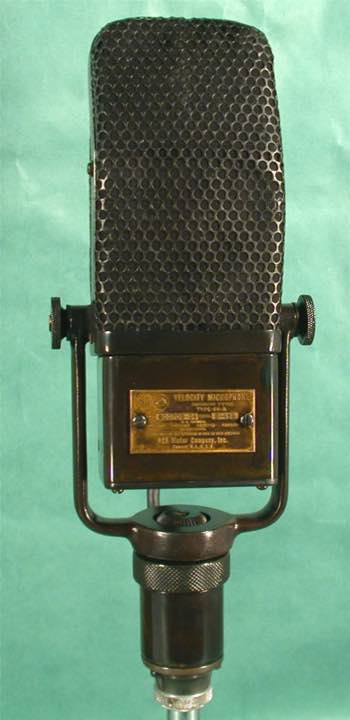
| Ribbon | A very thin corrugated metal ribbon hangs in a magnet's gap; air movement pushes it directly. | Smooth, figure-8 pickup. Early ones were delicate; some modern ones are tough. |
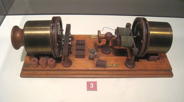
The history follows the physics. The carbon microphone, in which sound squeezes carbon grains and changes their resistance, was developed in the 1870s by Hughes, Edison and Berliner independently; Edison received the first patent in mid-1877, though Hughes had demonstrated a working device earlier. E. C. Wente of Western Electric built the first condenser microphone in 1916. Ribbon designs date from the 1920s, and RCA's 44 series, developed by Harry Olson's group, became a broadcast and recording standard in the 1930s. The electret condenser, invented at Bell Labs in 1962 by Gerhard Sessler and James West, keeps its polarising charge permanently, which is why a phone can afford a condenser capsule.


Condenser capsules are usually powered from the mixer or interface over the microphone cable itself, called phantom power: 48 volts, fed through two matched 6.81 kΩ resistors. The idea comes from telephone lines. Neumann's 1966 transistor microphone, the KM 84, shown to Norwegian broadcasting, is credited as the origin of the 48-volt version, which the IEC later standardised as P48. Most dynamic microphones are unaffected by phantom power, but a ribbon microphone's manual should be checked before it is switched on.
The 94 dB figure comes from the reference of 20 micropascals: 20·log₁₀(1 Pa ÷ 20 µPa) = 94.0 dB.
Polar patterns and the proximity effect
A bare diaphragm open to the air on all sides hears everything equally: that is an omnidirectional (omni) microphone. Open the back to the air as well, so the sound has to push the diaphragm from the front and also get around to its back, and the microphone responds to the difference in pressure between the two sides. That difference is largest for sound arriving along the axis and zero for sound arriving from the side. Mixing the two designs gives a family of patterns, all with one formula.
The cardioid takes its name from its heart shape and is the workhorse of the studio and stage because it rejects sound from behind: at 180° it is exactly 0.5 − 0.5 = 0. The hypercardioid is narrower at the front but has a small lobe at the back; its nulls sit at 109.5°, not behind. A figure-8 hears front and back equally and nothing from the sides. A negative number means the signal is upside down (reversed polarity), which will matter in a moment.
Pressure-gradient designs have a quirk. Close to a small source, the sound wave is strongly curved and its pressure drops off quickly with distance, so the gradient across the diaphragm is exaggerated, most of all at low frequencies. The result is a bass boost that grows as you move closer: the proximity effect. Singers use it on purpose to warm a voice. An omni has none. The model below is the ideal one, boost = √(1 + ((1 − A) ÷ kr)²) with k = 2πf ÷ 343 and r the distance in metres. Real microphones are engineered to tame it, so treat the numbers as the trend and not the specification.
Solid line: a signal in normal polarity. Dashed line (hypercardioid, supercardioid, figure-8 only): the rear lobe, which is inverted. DI is directivity index, the dB by which the pattern favours the front over sound arriving equally from everywhere.
Without JavaScript: a cardioid has response 0.5 + 0.5·cos θ, so it is 0.5 (−6 dB) at 90° and 0 at 180°. At 100 Hz and 2 cm the ideal model gives a cardioid about 22.7 dB of bass boost, 9.3 dB at 10 cm and 2.6 dB at 30 cm.
Distance: inverse square and the critical distance
In the open air, sound from a small source spreads over a sphere. Double the distance and the same power covers four times the area, so the level drops by 20·log₁₀(2) = 6.02 dB. That is the inverse-square law. A microphone at 1 m hears the source 6 dB quieter than one at 50 cm, and 20 dB quieter than one at 10 cm.
Indoors the law only half applies. The direct sound dies away with distance, but the sound that has bounced off walls fills the room at an almost even level. Close to the source the direct sound wins; far away, the room does. The distance where they are equal is the critical distance. In the standard diffuse-field approximation it is about 0.057·√(Q·V ÷ RT60), with V the room's volume in cubic metres, RT60 its reverberation time in seconds (the time for sound to die by 60 dB) and Q the directivity of the source or microphone. Past that distance, moving the microphone away does not make the source quieter relative to the room: it makes the room louder relative to the source.
A directional microphone listens more to the front, which stretches the critical distance by roughly √Q: about 1.7 times for a cardioid and 2 times for a hypercardioid. This is the real reason cardioids are popular. It is not that they ignore the room, it is that they let you stand farther back for the same ratio.
Illustrative rooms with round numbers. The diffuse-field approximation breaks down very close to walls and in rooms that are very dead or oddly shaped.
Without JavaScript: for a 30 m³ bedroom with RT60 0.4 s the critical distance for an omni is about 0.49 m, so a microphone 1 m away hears 6.1 dB more room than direct sound. A cardioid in the same room reaches about 0.85 m. A large church (10,000 m³, 4 s) has 2.85 m.
Two microphones and the 3:1 rule: phase and comb filtering
Put two microphones on one source and the sound reaches them at slightly different times. Sound travels about 343 m/s in air at room temperature, which is 34.3 cm per millisecond. If the second microphone is 34.3 cm farther away, its copy arrives 1 ms late. Mix the two and some frequencies line up (add) and others are opposite (cancel). The pattern of peaks and notches evenly spaced across the spectrum is a comb filter, named for what the frequency plot looks like.
For a 34.3 cm difference the first notch is at 500 Hz, and there are 20 notches below 20 kHz. They are deepest when the two signals have equal level. The cancelling shrinks as the farther microphone gets quieter, because a signal cannot cancel something louder than itself. That is the physics behind the 3:1 rule: keep microphones at least three times as far from each other as each is from its own source. Under the inverse-square law the farther one is then 20·log₁₀(3) = 9.5 dB quieter and the comb ripples shrink to between +2.5 dB and −3.5 dB. You will still hear a change, but not a hole.
Flip the polarity of one microphone (the "phase" button on a desk) and the notches move to different frequencies: the low end that cancelled now adds. Neither version is correct on its own. Engineers listen to both, which is why it is a button and not a rule.
Sound: a burst of noise plus its delayed copy, at the settings above. Keep the volume low. Without sound the plot still shows everything.
Without JavaScript: two equal-level microphones 34.3 cm apart cancel at 500 Hz, 1.5 kHz, 2.5 kHz and so on. At 3:1 (60 cm extra, 9.5 dB quieter) the first notch is at 286 Hz and the summed level swings between +2.5 and −3.5 dB.
Stereo: how two microphones make a picture
Two ears work out where a sound is from two cues: it is louder in the nearer ear, and it arrives there sooner. Stereo recording is the art of capturing the same two cues with two microphones. The main techniques differ in which cue they keep.
| Technique | Layout | Mostly captures |
|---|---|---|
| XY | Two directional microphones, capsules together, usually at 90° to 135° | Level differences only; no time difference, so it folds to mono cleanly |
| ORTF | Two cardioids 17 cm apart, angled 110° (named for French broadcaster ORTF) | Both cues, a stable image |
| Spaced pair | Two omnis apart, often 40 cm and up | Time differences; roomy and wide; mono sum can comb |
| Blumlein | Two figure-8s at 90°, capsules together | Level differences, plus the room from behind (the rear lobes) |
| Mid/Side | A forward microphone (mid) and a sideways figure-8 (side); left = M + S, right = M − S | Width you can change afterwards by turning S up or down; fully mono-compatible |
Alan Blumlein, an engineer at EMI, described the figure-8 pair in a British patent (394,325) based on an application made in 1931, together with much of the thinking behind stereo records. Mid/Side is the same idea rotated by 45° and re-wired. With the formula above you can predict how loud each channel gets for a source at any angle. That is what the toy below does, with a distant source so that only angle matters.
The two position bars are rules of thumb: a level difference of about 15 dB or a delay of about 1 ms is often quoted as enough to pull an image fully to one side. Real curves vary with the sound and the listener, and the two cues add.
Without JavaScript: with an XY pair of cardioids a source at 45° to the right reaches the right microphone at full level (1.00) and the left at 0.50, so the right channel is 6 dB louder. A 60 cm spaced pair hears a source 90° to the side 1.75 ms earlier at the near microphone.
Gain staging: signal, noise floor and headroom
A microphone's output is tiny. At 94 dB SPL the SM58 gives 1.85 millivolts, and a quiet voice gives a fraction of that. A preamp raises it to the level a converter expects, and the knob that sets how much is the gain. Every electronic stage adds hiss of its own, so the order of the game is simple: get the signal up high enough that the hiss behind it is small, and low enough that the loudest moment does not hit the ceiling.
The ceiling is hard in digital recording. In a converter, 0 dBFS (decibels relative to full scale) is the biggest value that exists; louder is clipped flat, and nothing fixes it afterwards. Broadcasters made this concrete: the European EBU R68 practice puts 0 dBFS at +18 dBu, so a level of −18 dBFS is the old "0 dBu" alignment tone, while American practice puts the alignment at −20 dBFS. There is no single standard, which is the point: aim to record at moderate levels, with peaks well under full scale. With 24-bit converters, the bottom of the range is far below any microphone's noise, so there is no reward for recording hot.
The noise floor has three sources: the microphone's own self-noise (a condenser quotes it in dB-A: the U 87 Ai rates 12 dB-A in cardioid, equal to the noise of a sound at 12 dB SPL), the preamp's equivalent input noise, and the converter. Gain raises the first two together with the signal. So the signal-to-noise ratio is set at the microphone: a quiet source far away from a noisy microphone cannot be rescued by turning the knob.
Assumptions, all round figures for illustration: preamp noise −128 dBu at the input, a converter with 110 dB of dynamic range, 0 dBFS equal to +18 dBu (the EBU R68 convention), and noise from the A-weighted self-noise figure added in power. Microphone sensitivities and self-noise are the makers' published specifications for the SM58 (sensitivity) and the U 87 Ai (sensitivity and noise).
Without JavaScript: the condenser at 94 dB SPL with 40 dB of gain lands at about −6.8 dBFS, with a noise floor near −88.7 dBFS, a signal-to-noise ratio of about 82 dB, which is just 94 minus its 12 dB-A self-noise. The dynamic microphone at the same settings sits at about −30.3 dBFS with roughly 74 dB of signal-to-noise.
The session: what actually happens in the room
A recording session is mostly preparation and listening. A sensible order is the one working engineers repeat so often it becomes habit: hear the source in the room first, with your own ears, and decide where it sounds best. Choose the microphone for the character you want, then place it and move it a hand's width at a time while someone plays and you listen on closed headphones or monitors. Set the gain from the loudest part, leaving room above it. Check polarity whenever two microphones share a source. Then make a short test take, listen back to it, and only then record the real one.
- Singers and plosives. Puffs of air from "p" and "b" overload a diaphragm; a pop shield a few centimetres in front of the microphone breaks the puff up without changing the tone much.
- Guitar amplifiers. A dynamic microphone close to the speaker cone and a condenser at a distance can be blended, and the 3:1 rule decides whether they fight each other.
- Drums. Many microphones, one kit: every one hears every drum. Position is part of the sound, and polarity checks are routine.
- Headphones and bleed. What one performer's headphones leak, the microphones pick up. Closed-back headphones and a lower monitor level help.
- The room is an instrument. A coat rack, a rug or a mattress behind a singer can change the recording more than a new microphone. See Room Acoustics & Studio Design (36/65).
- The person matters most. A nervous performer who is warm, fed and unhurried gives a better take than a perfect setup does. This is not a joke; it is a large part of the job.
What a graduate just sees
- A microphone is a point in a room, and its pattern tells you which parts of that room it listens to.
- Moving a microphone is the strongest equaliser you own, and it is free.
- Each doubling of distance costs 6 dB of direct sound, and past the critical distance the room takes over.
- Cardioids buy distance, not silence: they let you stand back by about 1.7 times for the same direct-to-room ratio.
- Proximity effect is real bass, and some singers use it as an instrument.
- Two microphones on one source mean delay, so check polarity and think in 3:1 terms.
- XY, ORTF, spaced and Mid/Side are choices about which stereo cue to keep and how well it folds to mono.
- Set the gain so peaks stay well under 0 dBFS and the noise stays far below the signal; do not hunt for hot levels.
Where it shows up next
- Digital Audio & the DAW (36/62): the preamp's output meets the converter, and sampling and bit depth decide what survives.
- Mixing & Signal Processing (36/63): equalisation and compression repair or flatter what the microphone gave you, but the choice of microphone and position decides how much repair is needed.
- Room Acoustics & Studio Design (36/65): the direct-to-room ratio you just played with is a property of the room, and rooms can be built to change it.
- Live Sound Reinforcement (36/66): the same patterns decide how much gain you get before a stage microphone feeds back, which is why monitors sit on the null.
- In the world: podcasts, orchestral recordings, field recordings of ceremonies and of birds, voice-over booths, film dialogue (boom microphones are narrow, directional designs pointed at the actor's mouth).
If you want to go deeper
- 📘 Textbook. David Miles Huber, Emiliano Caballero and Robert Runstein, Modern Recording Techniques (10th edition, Focal Press/Routledge, 2023), the book most audio-programme syllabi assign; it covers microphones, the studio and the digital chain together.
- 📘 Microphone reference. Ray Rayburn, Eargle's The Microphone Book (Focal Press), the standard detailed text on transducers, patterns and stereo techniques.
- 🌐 Gentler. The free tutorials and techniques articles at Sound On Sound, written by working engineers for people learning on their own.
- 🌐 Free course. MIT OpenCourseWare 21M.380 Music and Technology: Recording Techniques and Audio Production, with syllabus, readings and assignments.
Recording is choosing a place in a room to listen from. The pattern says what the microphone hears, the distance sets the balance of source and room, a second microphone adds delay, and the gain decides whether the noise or the ceiling gets there first. Get those right at the source and everything later is easier.
Try this: record the same sentence on your phone at 15 cm, at 60 cm and across the room, in a bare kitchen and then in a room with a bed or a sofa. Listen on headphones for the point where the voice stops sounding close and starts sounding like the room.
Sources. Microphone history: Wikipedia, "Microphone" and "Ribbon microphone" (Hughes, Edison and Berliner carbon microphones; Wente 1916; RCA's 44 series and Harry Olson; Sessler and West 1962); "Phantom power" (IEC 61938 P12/P24/P48; 6.81 kΩ resistors; Neumann KM 84 and Norwegian broadcasting, 1966). Specifications: Shure SM58 (−54.5 dBV/Pa, 1.85 mV/Pa; produced since 1966) and Neumann U 87 Ai product pages (28 mV/Pa cardioid, 12 dB-A, 117 dB maximum SPL). Patterns, directivity index and proximity effect: standard pressure-gradient microphone theory (first-order pattern A + (1 − A)·cos θ; random-energy efficiency A² + (1 − A)²/3), computed here. Critical distance: Wikipedia, "Critical distance" (0.057·√(γV/RT60)). 3:1 rule: Wikipedia, "Microphone practice". Stereo: Wikipedia, "Stereophonic sound" (ORTF 17 cm and 110°; XY; Mid/Side; spaced pair ≈ 1.75 ms at 60 cm) and "Blumlein Pair" (British patent 394,325, application 1931). Alignment levels: Wikipedia, "DBFS" (EBU R68, +18 dBu at 0 dBFS; American practice −20 dBFS). Every number shown by the interactives and in the prose was computed in node.
- 📘 Huber, Caballero and Runstein, Modern Recording Techniques
- 📘 Rayburn, Eargle's The Microphone Book
- 🌐 MIT OCW 21M.380